

Conical Compression Springs
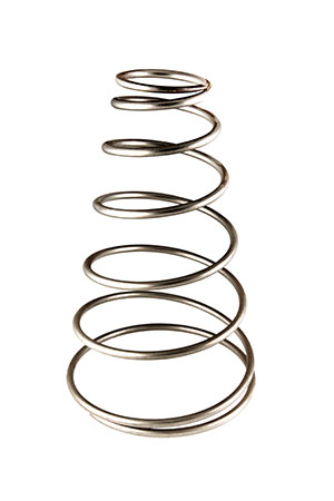
Conical Compression springs are often specified where the large end is meant to work in a bore and the small end is meant to work over a rod. They offer the advantage of a reduced solid height compared to straight compression springs, especially when capable of "telescoping."
Conical Springs are Cone shaped compression springs designed to provide a near constant spring rate and a solid height lower than a normal spring. Each spring features a variable pitch to achieve the constant spring rate and coils which nest during deflection to provide a solid height approximately equal to two wire diameters.
Need a quote for conical compression springs? Click here to get one today.
Some uses for conical compression springs are as follows:
Small Solid Height: A Conical spring can be designed so that each active coil fits within the next coil, so the solid height can be equal to one or two thicknesses of wire. This is useful where the solid height is limited.
Variable Rate: These springs offer a constant, or uniform pitch, and have an increasing force rate instead of a constant force rate (regular compression springs). The larger coils gradually begin to bottom as a force is applied. A variable pitch can be designed to give a uniform rate if necessary.
Stability: Conical compression offers more lateral stability and less tendency to buckle than regular compression springs.
Vibration: Resonance and vibration is reduced because Conical Compression springs have a uniform pitch and an increasing natural period of vibration (instead of a constant) as each coil bottoms.
Vibration: Resonance and vibration is reduced because Conical Compression springs have a uniform pitch and an increasing natural period of vibration (instead of a constant) as each coil bottoms.
Design Specs
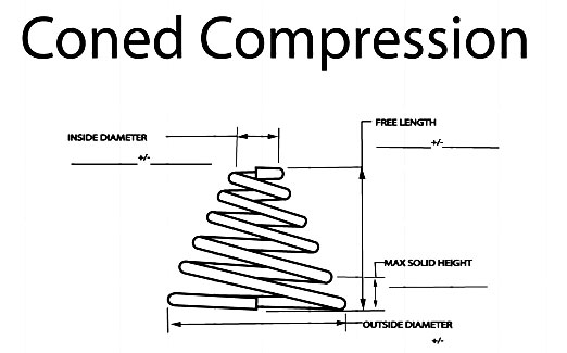
Whether you are developing a conical compression spring design or simply ordering your springs, it is important that you provide the following spring specifications and information.
-
Free Length, Maximum, Minimum.
-
Controlling Diameter, Outside Diameter Maximum. Inside Diameter Minimum. Pitch Diameter. Works Inside (Dia. Hole). Works Over (Dia. Shaft).
-
Number of Coils.
-
Wire Size. Decimal size if possible. Material, Kind and Grade.
-
Loads at deflected positions.
-
Style of Ends, (see illustrations). Right or Left Hand Wound.
-
Finish. Plain unless otherwise specified.
-
Maximum Solid Length.
-
Frequency of Compression.
How to Determine Rate For Conical Compression Springs
Conical Compression change in load per unit deflection, may be determined by the following procedure:
-
Deflect spring to approximately 20 percent of available deflection and measure load (P1) and spring length (L1).
-
Deflect spring to approximately 80 percent of available deflection and measure load (P2) and spring length (L2). Be certain that no coils (other than closed ends) are touching L2.
-
Calculate rate (R) lb./in. (N/mm)
R = (P2 - P1) / (L1 - L2)
Solid Height
The solid height of conical compression springs are defined as the length of the spring when under sufficient load to bring all coils into contact with the adjacent coils and additional load causes not further deflection. Solid height should be specified by the user as a maximum, with the actual number of coils in the spring to be determined by the spring manufacturer.
As square or rectangular wire is coiled, the wire cross-section deforms slightly into a keystone or trapezoidal shape, which increased the solid height considerably. The dimensional change is a function of the spring index and the thickness of the material.
Conical Compression Pitch
A uniform pitch in a conical spring is far easier to make then a variable pitch. During testing, if no coil bottoms, a straight-line force curve versus deflection occurs similar to that of a compression spring. When the largest active coil bottoms, an upward slope of the force curve occurs. The maximum force occurs when all coils have bottomed. The calculation to determine the force at the solid position can be easily performed by using the regular formula for compression springs and using the mean diameter of the smallest active coil only; N equals 1.
Grinding
Grinding the end coils of conical springs is done in a different manner. Some specifications call for grinding only the small end coil. Others require grinding on both ends. Grinding in either case is difficult and expensive. Grinding small, medium and large quantities may be done as explained for regular compression springs except that when using double wheel grinders it is necessary to make special turntables with holes shaped like the conical springs. Making a large amount of tapered holes to hold the springs is not easily done and may require making special coned reamers to cut the holes. For this reason, hardwood platens, in place of steel are often used.
Cautions
1. Extra time for all manufacturing operations should be considered when estimating the costs of making coned conical compression springs or for any springs requiring special material, square or rectangular wire, or special testing.
2. Variable pitches in a conical spring are occasionally specified so that all active coils bottom simultaneously, but this is seldom achieved.
3. Grinding is especially difficult and time-consuming. Special fixtures may be required. The cost of grinding discs should be included for large quantities of springs.
4. Tangling of highly pitched springs made from small diameters of wire up to 1/16 inch (1.5 mm) having rather large base diameters often occurs and may require special handling during secondary operations and for packaging.
Spring Design
Conical Compression Spring Design
There are several methods of analyzing the complex stresses in conical compression springs depending upon the type of pitch, angular relationship of the coils, constant slope, curving contours, and other factors. Analyzing all of the variables and solving for stresses, deflections, and forces can be a mathematician's delight and a playground for higher mathematics, but spring manufacturers can ill afford to devote valuable time to such matters and many use a simplified solution that quickly and easily provides a suitable wire size and number of active coils, as follows:
Approximate Method
First, calculate the average outside diameter. This can be done in several ways depending upon the diameters specified. The easiest way is to add the outside diameter of the top end to the outside diameter of the base and divide by 2. Adding the OD of the base to the ID at the top of dividing by 2 will provide the average D. Second, calculate the approximate force at the solid height. Third, locate the average OD and find a force, deflection per coil and a wire size and proceed with calculations in the same manner as for regular compression springs. This method should be used with care if large deflections cause coils to bottom early.
Exact Method
MA more exact method is first to determine the wire size and number of coils by the approximate method and then analyze the force, deflection, and stress of each individual coil and make adjustments to the design to meet the requirements. This may require a large number of individual calculations for each spring, but should be done for large, important springs and where a long fatigue life may be needed.
Videos
These videos show how conical compression springs are manufactured.
For more information about conical compression springs or to talk to one of our experts call 1-800-828-3353 .